Is there any information on how to solder a ESP32 Wemos onto the Dimmy?
I.e., which pins do you connect to the dimmy? There’s an inner row and outer row of pins. I am confused on which need set of pins need to be connected to the Dimmy. Is there any information on setting this up?
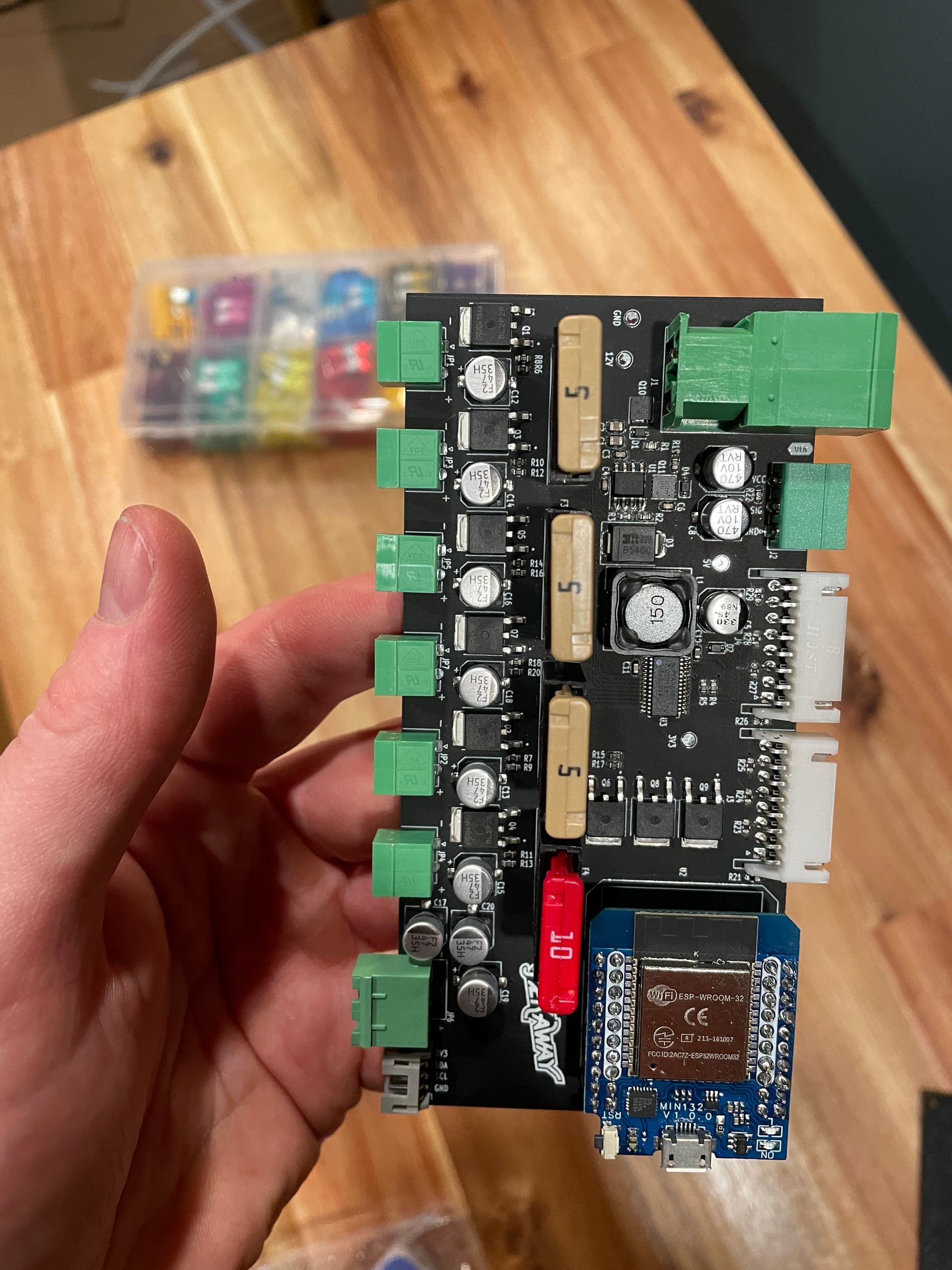
I have the same problem. On the Dimmy there are over the connectors all 40 Pin available. Should I also use all PIN’s on my wemos D1Pro ESP32?
I haven’t been able to find usefull documentation on it. In the Circuit diagram I do see that not all PIN are used but on the circuit board all PIN’s are named the same as on my Wemos. Therefore I have deceided that I also will use all 40 PIN.
So I will use something like - Pin Header Male 2 X 40 Pin RM 2.54mm Straight Short Pin - and cut it in half.
Et Voilà
I will let you know as soon as I’m done.
Manfred
Hello! Thanks for the response. I also ended up soldering all the pins from the wemos to the dimmy. I was able flash the tasmota image and connect to my vans wifi network (supplied by an LTE router - same as what the VanPi is connected to). However, i’ve had trouble getting the dimmers and temp sensors to work. I am fairly certain it’s connected to the same network but there’s been no response. @Vincent Any suggestions on how to debug? Thank you!
@aballingall Are you able to open up Tasmota under the Wemos’ IP-adress?
If so, you should be able to set the dimmers in the tasmota console by using the command pwm,0,500, with 0 being the channel number (0-6, for channels 1-7) and 500 being the value of the channel (0-4095, 0 for off and 4095 for 100%).
You could also try to send the MQTT commands by hand using pkw/cmnd/PekawayMOTA/driver15 as the topic and pwm,0,500 as the payload.
If the dimmy is in the same network, you should see data coming in from Tasmota as well.
Also, the tempsensors should show up on the mainpage of Tasmota.
For soldering, you need both, the inner and the outer pins, if you want to use the GPIO Inputs of the Dimmy. If you don’t use the inputs, then the inner pins only would be sufficent. It wouldnt hurt to solder all available pins anyway.
Hi @Vincent , Thanks for the response. It looks like there’s an issue with connecting to the broker. Tried to re-download firmware but same result. Any suggestions on how to fix?
Here’s the logs from the console:
00:00:00.002 HDW: ESP32-D0WD-V3
00:00:00.043 UFS: FlashFS mounted with 304 kB free
00:00:00.078 CFG: Loaded from File, Count 11
00:00:00.091 I2C: Bus1 using GPIO22(SCL) and GPIO21(SDA)
00:00:00.098 TFS: File ‘mcp23x.dat’ not found
00:00:00.225 BRY: Berry initialized, RAM used=3922 bytes
00:00:00.245 TFS: File ‘.drvset003’ not found
00:00:00.246 CFG: Energy use defaults as file system not ready or file not found
00:00:00.254 Project PekawayMOTA - PekawayMOTA Version 12.5.0.4(tasmota32)-2_0_10(2023-06-19T17:53:07)
00:00:00.267 I2C: PCA9685 found at 0x55
00:00:00.944 WIF: Connecting to AP1 Seaton_Vans Channel 6 BSSId 20:97:27:42:B1:AB in mode 11n as PekawayMOTA-2148…
00:00:02.683 WIF: Connected
00:00:02.948 HTP: Web server active on PekawayMOTA-2148 with IP address 192.168.1.179
21:41:06.068 RSL: SENSOR = {“Time”:“2024-12-31T21:41:06”,“PCA9685”:{“PWM_FREQ”:200,“INVERT”:0,“PWM0”:0,“PWM1”:0,“PWM2”:0,“PWM3”:0,“PWM4”:0,“PWM5”:0,“PWM6”:0,“PWM7”:0,“PWM8”:0,“PWM9”:0,“PWM10”:0,“PWM11”:0,“PWM12”:0,“PWM13”:0,“PWM14”:0,“PWM15”:0,“END”:1}}
21:41:06.163 MQT: Attempting connection…
21:41:06.184 MQT: Connect failed to pekaway.local:1883, rc -2. Retry in 10 sec
21:41:17.151 MQT: Attempting connection…
21:41:17.173 MQT: Connect failed to pekaway.local:1883, rc -2. Retry in 20 sec
21:41:38.802 MQT: Attempting connection…
21:41:38.822 MQT: Connect failed to pekaway.local:1883, rc -2. Retry in 30 sec
21:42:10.021 MQT: Attempting connection…
21:42:10.038 MQT: Connect failed to pekaway.local:1883, rc -2. Retry in 40 sec
21:42:23.969 CMD: pwm,0,500
21:42:23.972 RSL: RESULT = {“Command”:“Error”}
@Vincent I set the IP-address to the RPI address and it didn’t work. Using Chat GPT it told me to add the following under sudo nano /etc/mosquitto/conf.d/local.conf
listener 1883
allow_anonymous true
After doing so the dimmy was successfully connected to the RPi and i am able to control the dimmers via wifi. However, no temperatures are displayed. Any suggestions for getting those to work?
Hi, i got the temperature sensor to be displayed by the dimmy. I needed to change the GPIO 16 in the config module to DS18x20 and 1.
Still not sure if changing the settings in sudo nano /etc/mosquitto/conf.d/local.conf to allow non password connections is okay? but everything seems to work now.
Hello aballingall
First I tried the connect web tool but it never got out of the “prepare to install” routine.
Therefore I have used the vanpi relay board to write the esp32 on my dimmy.
I have chosen the esp32 standalone routine. It is uploading and comes back with an “flash ok” message. Nevertheless after rebooting the whole system . Power off / on. I still can’t use the GPIO Pin to switch on/off or dimm.
I have all PIN used to connect the ESP-Wroom-32 to the dimmy and it looks exactly the same as your version.
I have no experience or clue how to work with the esp32 I hoped it will just work as others have used it that way.
When I uploaded the WIFI version it did work but that and the wired version aren’t supporting the GPIO - which is a shame as this would be the perfect integration. Switch, app and display control - all doing the same thing.
Thanks for any hint
You’re correct, we need that line in the mosquitto configuration. I remember they made that change a few years ago, I just forgot it in the init-script, sorry about that.
No password and non-encrypted connections are fine as long as it stays within your private network. If your network gets compromised with ill intent, then your mqtt messages could be accessed, but you’ll probably have other problems then
Hallo Vincent
Ist zwischen der Dimmy Version welche mit der 1.0.2 Version via Relaisboard auf das Dimmy gespielt werden kann und der 2.0.4 Version ein Unterschied?
Ich habe die Standalone Version auf das ESP gespielt aber die Schalter funktionieren nicht. Das Flashen ab Relaisboard V2.0.4 funktionier nicht mehr deshalb kann ich keine neuere Version aufspielen. (Web Flash Tool geht auch nicht dieses hat das Gefühl, dass die Schnittstelle bereits benutzt ist).
Danke
Manfred